
HDD crews do not see buried utilities while the drill head moves underground. They read electromagnetic fields and infer where the utility lies. That difference matters. A clean field can guide a safe bore. A distorted field can move the apparent centerline, hide a deeper line, or make the wrong conductor look like the target. The research shows one practical rule: passive locating helps crews find risk, active locating helps crews identify a target, and exposure removes the last uncertainty at critical crossings.
This article turns the research into a field-ready guide for utility locators, HDD crews, inspectors, and equipment buyers in the U.S. market. It explains where active and passive interference come from, how crews can spot it, and which equipment features help teams manage it before the bore enters a tolerance zone.
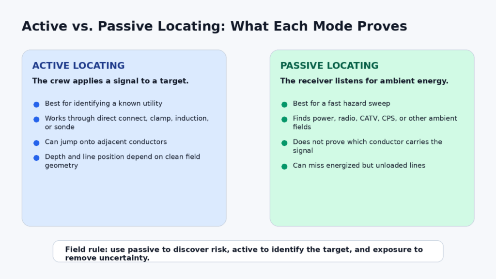
The Core Difference: What Each Mode Can and Cannot Prove
Active locating starts when the crew applies a known signal to a utility. The signal can enter the target through a direct connection, a clamp, induction, or a sonde. Active locating gives the crew the best chance to identify a specific line, but the signal can still bleed onto a nearby conductor, return through unexpected paths, or distort near dense metal.
Passive locating works in the opposite direction. The receiver listens for energy already present in the ground: power-frequency current, radio-frequency energy, CATV signals, cathodic-protection systems, or other ambient sources. Passive mode helps crews sweep a corridor quickly, but it does not prove which conductor carries the signal. A gas line, pipe, cable shield, rebar grid, or fence can all carry coupled energy.
Why Interference Misleads HDD Crews
The research points to two separate problems: signal contamination and field-shape distortion. Signal contamination happens when the active signal jumps to an adjacent utility or when passive energy appears on several conductors at once. Field-shape distortion happens when nearby metal bends the electromagnetic field. The receiver then reports a centerline and depth based on a field that no longer matches the target line.
This is why “strongest signal” is a weak decision rule. The strongest response may come from a shallow parallel utility, a common trench, rebar, a guardrail, a cathodic-protection path, or a return-current path. The locator can look confident while the field lies.
The field gets less reliable when crews use high power, broad induction, or a frequency that couples well to multiple conductors. Lower frequencies usually stay on the target better but may be harder to detect on poor conductors. Higher frequencies can be easier to pick up but often jump more readily to adjacent metal. Crews need to change frequency and coupling method when the signal stops behaving like a single utility.
Field Conditions That Create Bad Locates
Dense utility corridors create the highest risk. Fiber, gas, water, telecom, power, CATV, and abandoned lines often run parallel, cross at shallow separation, or share a trench. A transmitter can energize more than one conductor. A shallow line can mask a deeper target. A mark can then shift several inches or feet from the true utility.
Ambient-clutter sites create a different problem. Substations, transformers, overhead distribution, electrified rail, metal fences, guardrails, reinforced concrete, and cathodic-protection systems can make the receiver respond almost everywhere. Passive mode may show too many candidates. Active mode may overload or show multiple believable alignments.
Nonmetallic or poorly conductive utilities create the opposite failure mode: not enough useful signal. PVC, fiberglass, vitrified clay, abandoned lines, empty conduits, and metal pipe with insulating joints may not carry an EM signal in a way the receiver can trace. Crews then need a sonde, trace rod, tracer wire, GPR, or vacuum exposure.
Multi-operator fiber builds add another modern source of interference. Several crews may apply locate signals in the same corridor. Frequency shifting, noise measurement, and coordination between crews matter when multiple locators work in the same bandwidth.
Symptoms That Should Stop the Bore
Interference usually announces itself before crews know the cause. The safe response is not to average bad readings. The safe response is to stop, change the setup, and prove the line again.

The fastest check is the depth verification test. Place the receiver over the target and read depth. Raise the receiver about 6 inches. A clean field should increase the displayed depth by about 6 inches. If the number barely changes or jumps, the field may be distorted or too weak for a safe interpretation.
A Safer Locate Workflow for HDD Crossings
The strongest field practice uses several independent checks. Records and 811 marks start the job, but they do not finish it. The crew still needs a passive sweep, active confirmation, distortion checks, and exposure where the bore crosses a known or suspected utility.

This workflow follows the logic behind ASCE 38. Geophysics can designate an approximate horizontal utility position. Exposure confirms the precise location. HDD crews need that distinction because the drill head can damage a utility without the visual feedback that open-cut excavation provides.
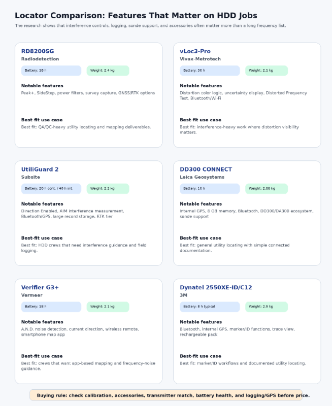
Equipment Features That Matter More Than a Long Frequency List
A long frequency list does not protect a crew if the receiver cannot show distortion, current direction, overload, or uncertainty. For interference-heavy HDD work, the research gives more weight to these features:
- current direction, to separate the target from a coupled conductor;
- peak/null comparison or distortion views, to reveal field-shape problems;
- noise or ambient-interference measurement, to choose a quieter frequency;
- frequency-shift tools and power filters, to avoid nearby locate signals or mains harmonics;
- sonde and beacon support, to trace nonmetallic pipe, ducts, and conduits;
- logging, GPS, or RTK, to document the interpreted line and support QA/QC.
When crews compare Underground Magnetics locating equipment, they should check the whole field system: receiver, transmitter, clamps, sonde options, frequency control, and documentation tools. Stated depth and price matter, but interference controls decide whether the crew can trust the mark in a crowded corridor.

What the Damage Record Shows
The Common Ground Alliance HDD data subset analyzed 9,054 HDD-related reports for 2021. Locating was the leading root-cause group. Within HDD excavation-practice failures, failure to pothole or maintain clearance led the list. The “locator error” label often hides deeper causes such as bad maps, tracer-wire problems, abandoned facilities, or an ambiguous field that crews accepted too quickly.
Public incidents show the stakes. In Canton, Illinois, the NTSB found that directional drilling damaged a marked gas line before a natural-gas explosion killed one worker and injured eleven people. The NTSB highlighted the contractor’s decision not to excavate the utility crossing and visually inspect the work while drilling. In Durham, North Carolina, a horizontal-boring job breached a gas service line before an explosion killed two people and injured about twenty-five. CGA trenchless guidance also cites serious HDD gas-line incidents in Waxahachie, Ewing, and Kansas City.
These cases do not all prove electromagnetic interference as the single cause. They prove the field risk that matters most to HDD crews: when a locate remains ambiguous, exposure and verification are the reliable escape path.
Practical Rules for HDD Crews and Equipment Buyers
Start every bore corridor with a passive sweep. Use it to find conductive risk, not to identify the line. Then actively trace known utilities from the cleanest connection the crew can get. Direct connection or a clamp usually gives more control than broad induction. If the line sits in a crowded corridor, use lower power, try another frequency, and compare peak, null, current, and depth behavior before you mark.
Expose critical crossings and tolerance zones before the drill passes. A good EM locate narrows uncertainty. It does not replace potholing where a utility crossing can cause injury, service loss, fire, or project shutdown.
Equip the crew for mode changes. A receiver without clamps, direct-connect leads, a matched transmitter, a ground stake, a sonde, and a calibrated accessory set leaves the team with too few choices when the field turns ugly. Used equipment can work well, but only when the buyer verifies calibration, battery health, firmware, accessories, and frequency compatibility.
Common Errors That Raise Interference Risk
- Trusting passive mode as identification instead of using it as a sweep.
- Turning up transmitter power when the signal is already coupling to nearby metal.
- Marking the strongest response without checking current direction, peak/null agreement, or depth behavior.
- Ignoring nonmetallic utilities, private services, abandoned lines, and damaged tracer wires.
- Using GPS or RTK to document a distorted locate as if better coordinates fixed the electromagnetic error.
- Skipping exposure because the mark looks clean on one pass.
The fix is operational, not theoretical: compare modes, change the coupling setup, retest depth, document the result, and expose the crossing when the field still does not behave.
DEEPER DIVE: Read all the Ranking Arizona Top 10 lists here
INDUSTRY INSIGHTS: Want more news like this? Get our free newsletter here
Bottom Line
Active locating and passive locating solve different problems. Passive mode helps the crew discover conductive risk across the bore path. Active mode helps the crew identify a target utility when the applied signal stays controlled. Neither mode can overcome a distorted or masked field by itself.
The safest HDD crews treat a locate as evidence, not truth. They sweep, confirm, check distortion, adjust the setup, and expose critical crossings. That sequence turns interference from a hidden failure mode into a manageable field condition.
Research basis
This article is based on the supplied research document and its cited sources: CGA 2021 DIRT HDD data, FHWA utility-locating guidance, ASCE 38, NTSB and municipal incident materials, and manufacturer documentation from Radiodetection, Vivax-Metrotech, Subsite, Leica Geosystems, Vermeer, RIDGID, and 3M.