
In the world of hardware engineering, we often say that a system is only as reliable as its weakest point of contact. While a Contact Pin might seem like a simple commodity, it is actually a masterpiece of micro-engineering. It must balance mechanical spring force, electrical conductivity, and chemical resistance—all while fitting into increasingly smaller footprints.
Choosing the right pin isn’t just about looking at a datasheet; it’s about predicting how that pin will behave after 5,000 mating cycles or three years in a high-humidity environment. This guide dives into the technical nuances that separate high-performance interconnects from “good enough” components.
What is a Contact Pin?
At its core, a Contact Pin is the physical interface that allows electricity or signals to bridge the gap between two independent circuits. Whether it’s a terminal in a heavy-duty automotive harness or a microscopic probe in a high-frequency testing socket, the pin’s primary job is to maintain a stable, low-resistance connection.
From an engineering perspective, we view a contact pin as a dynamic mechanical component. It has to handle “Normal Force”—the pressure required to break through surface oxides—while ensuring it doesn’t cause excessive wear on the mating surface. A well-designed pin accounts for thermal expansion and vibrational stress, ensuring that “signal jitter” doesn’t become a nightmare for the end-user. In high-speed digital applications, the pin even acts as a transmission line where geometry dictates impedance.
Main Types of Contact Pins
Not all interconnect challenges can be solved with a one-size-fits-all approach. Depending on your mechanical constraints and signal requirements, you’ll likely find yourself choosing between these four major architectures:
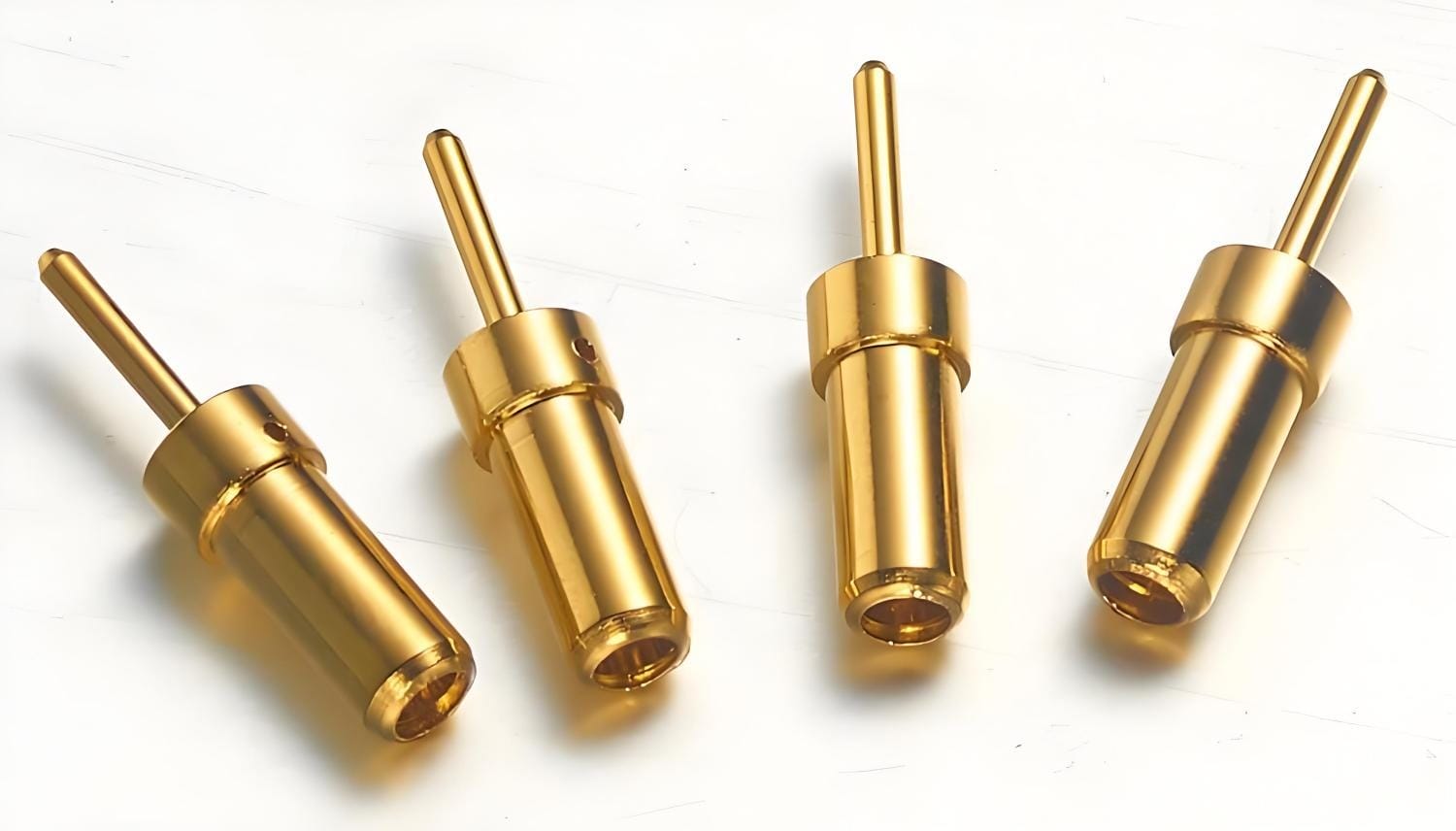
1. Pogo Pins (Spring-Loaded Pins)
These are the workhorses of the consumer electronics world. Consisting of a plunger, a barrel, and an internal spring, they provide a “cushioned” contact. The real secret to a high-quality pogo pin lies in the internal design—using a slanted plunger or a ball-point interface to ensure the plunger always maintains contact with the barrel wall. This prevents “instantaneous open circuits” during high-vibration events.
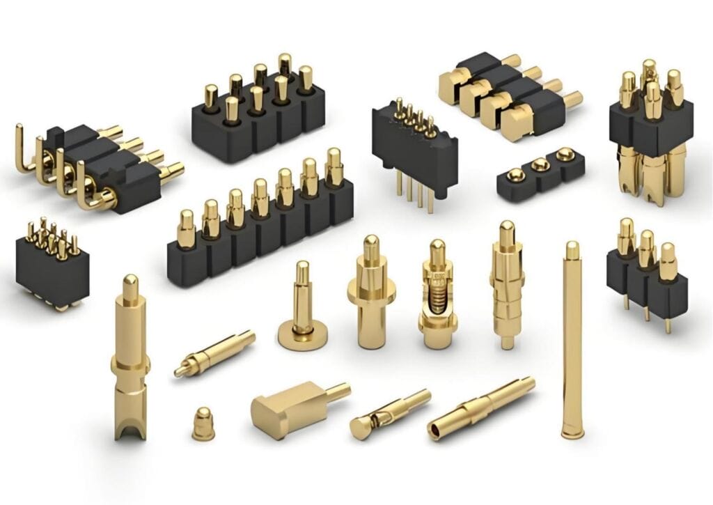
2. Solid Machined Pins
When you need high current-carrying capacity and absolute physical robustness, solid pins are the standard. Because they are turned from solid bar stock, they offer superior dimensional stability and a 360-degree contact surface that is ideal for heavy-duty industrial connectors and power-dense applications.
3. Press-Fit Pins
These are designed for “cold-weld” assembly. By pressing the pin into a slightly smaller plated-through-hole (PTH) on a PCB, you create a gas-tight connection without the need for solder. This is a game-changer for high-layer-count boards where the thermal stress of wave soldering could damage internal traces or delicate surface-mount components.
Why Low-Cost Plating Fails
This is where most competitors cut corners. You might see “Gold Plated” in a quote, but the devil is in the porosity.
- The Problem: Cheap plating often has microscopic voids. Under humidity, the base copper migrates through these pores, leading to fretting corrosion. This results in “ghost failures”—signals that work one minute and fail the next.
- The Fix: We prioritize Nickel under-plating as a diffusion barrier. By controlling the grain structure of the gold deposit, we ensure a non-porous shield that keeps contact resistance stable for years, not months.
DFM: Engineering the “Nightmares” Out of Your Design
I’ve seen countless projects delayed because a pin looked great in CAD but was impossible to assemble. Here are three “Real World” tips:
- Stop Designing “Square” Shoulders: Always use a lead-in chamfer. If your pin tail doesn’t have a taper, your automated optical inspection (AOI) will flag a high percentage of “misalignments.”
- Mind the Normal Force: For spring pins, ensure your compressed height doesn’t exceed the “working travel” limit. Over-compressing lead to spring fatigue and permanent set.
- Co-planarity Matters: For SMT (Surface Mount) pins, if your tails aren’t flat within a tight tolerance (usually $<0.1mm$), you’ll get “open” joints that are a nightmare to rework.
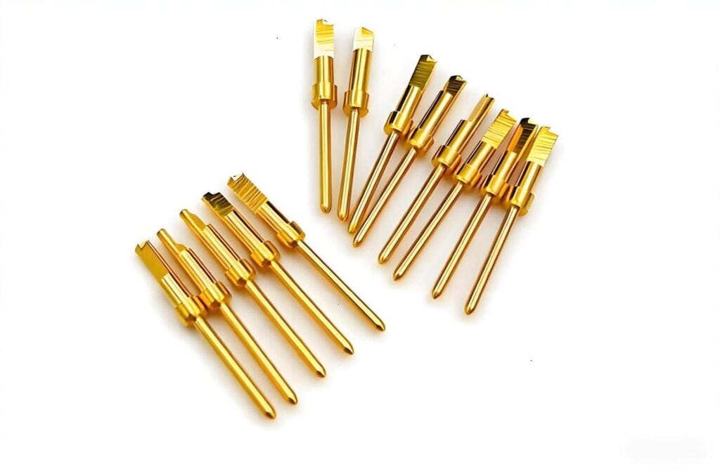
Core Processing Methods for Contact Pins
The way a pin is manufactured dictates its precision, its surface finish, and ultimately, your total cost of ownership.
- CNC Precision Turning: This is the “gold standard” for high-complexity pins. Using precision swiss machining, we can achieve tolerances as tight as $\pm$0.01mm. This process ensures no “parting lines” or burrs. This is critical because a tiny burr on a pin can act like a knife, shaving off the gold plating of a female socket during insertion and causing premature failure.
- Stamping & Forming: For high-volume commodity parts, stamping is king. It’s incredibly fast and cost-effective. However, engineers must be wary of “stamped edges,” which are naturally abrasive. High-end stamped pins often require secondary electropolishing to prevent excessive wear on mating interfaces.
- Cold Heading: This involves “moving” metal rather than cutting it. It’s excellent for producing large volumes of solid pins with very little material waste. It is the most sustainable and cost-efficient method for mass-market automotive terminals where material cost is a primary driver.
Application Scenarios of Contact Pins
In the field, a contact pin isn’t just a part; it’s the physical layer of the signal path. Its performance dictates the reliability of the entire system architecture across these primary sectors:
Consumer Electronics
Beyond standard connectivity in smartphones and wearables, we focus on dynamic tolerance compensation. Spring-loaded pins (pogo pins) are utilized here not just for mating cycles, but to handle “z-axis” stack-up height variations in ultra-slim assemblies, ensuring consistent contact force despite mechanical tolerances.
Automotive Electronics
The transition to EVs has pushed requirements into the extreme. Pins in Battery Management Systems (BMS) and ECUs must mitigate fretting corrosion caused by engine harmonics and chassis vibration. We design for a wide thermal envelope (typically -40°C to 150°C), prioritizing alloys that maintain their “normal force” without stress relaxation over the vehicle’s 15-year lifecycle.
Industrial Machinery
For M8/M12 automation interfaces, the priority is ruggedization and ampacity. Pins must handle high-density current loads and survive high-pressure washdowns (IP69K environments). We often specify thick hard-gold over-plating to resist abrasive wear in dusty, high-cycle factory floor applications.
Medical Devices
Here, the challenge is biocompatibility and low-level signal integrity. For diagnostic imaging or patient monitoring, pins must withstand harsh sterilization cycles (autoclave or chemical wipe-downs) without plating degradation. We focus on gold-thickness optimization to ensure that micro-volt signals from biosensors aren’t lost to contact resistance.
Aerospace & Defense
Reliability in these sectors is non-negotiable. Components must withstand vacuum outgassing and extreme G-loads. We specify high-reliability machined pins, often utilizing specialized base metals like Berrylium Copper or titanium alloys, ensuring the interconnect remains gas-tight under rapid atmospheric pressure changes.
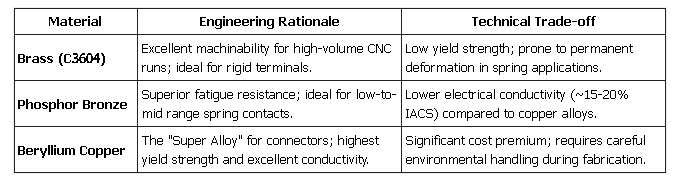
Contact Pin Material Selection Guide
Material science is the foundation of pin reliability; you aren’t just selecting a metal, you are defining the “spring rate” and electrical stability of the interface.
Technical Trends and Industry Challenges
We are currently pushing against the “precision ceiling” as the industry moves toward 0.3mm pitches and sub-millimeter form factors.
- Miniaturization: At 0.4mm pitches and below, the mechanical “wipe” of a connector is minimal, making surface finish critical. Since traditional calipers and micrometers cannot validate these geometries, we utilize high-speed Automated Optical Inspection (AOI) and laser interferometry to ensure the dimensional integrity of every batch.
- Signal Integrity at High Frequencies: In 5G/6G RF paths, the pin’s physical geometry introduces parasitic inductance. We no longer treat the pin as a wire; we treat it as a coaxial element. By using Finite Element Analysis (FEA), we tune the pin’s impedance to match the system, minimizing insertion loss and return loss at GHz frequencies.
- Sustainability & Compliance: Tier-1 supply chains now demand full transparency. Beyond RoHS and REACH, we are seeing a shift toward Lead-Free (C3604-compliant) brass and circular economy sourcing. Providing a comprehensive Material Data Sheet (MSDS) is now a baseline technical requirement, not an added value.
Conclusion: Choosing a Partner in Precision
In high-reliability interconnects, there is no such thing as a “minor” component. The difference between a stable system and a field recall often comes down to 50 micro-inches of nickel plating or the radius of a lead-in chamfer.
As we move toward higher data rates and smaller footprints, the “good enough” approach to component sourcing creates unacceptable risk. A holistic design strategy—one that integrates material science, precision CNC machining, and rigorous DFM (Design for Manufacturing) protocols—is the only way to ensure the long-term survival of your hardware in the field. By prioritizing quality at the pin level, you are fundamentally de-risking your brand’s reputation and ensuring the safety of your end-users.
Author: Mars is a leading technical expert at Richconn-cnc with over a decade of hands-on experience in precision CNC machining and interconnect component R&D. Specializing in high-frequency and high-current applications, he has spearheaded complex contact pin solutions for the automotive and industrial automation sectors. Mars leverages his deep knowledge of material science and DFM to help global hardware engineers balance peak performance with scalable production costs.