Arizona developers are planning data centers for high-density computing, including projects that use direct-to-chip liquid cooling. Yet these designs still require airflow management wherever equipment remains air-cooled. Supply air must reach equipment intakes without taking unintended shortcuts, and warm exhaust needs a reliable return path.
During a retrofit, those paths meet cabinets, cable trays, containment panels, doors, and floor openings. Their edges rarely form one repeated shape. A rack brush panel may solve a standard rack opening, but other gaps require different closures. Identify the airflow boundary, then choose for its geometry and maintenance routine.
Follow the airflow boundary beyond the rack
ASHRAE’s data center guidance explains two air-mixing problems: cool air bypassing equipment and hot exhaust recirculating into equipment intakes. To assess a visible opening, identify the air paths and pressure difference on either side. A gap within one air zone may matter less than a smaller gap across the containment boundary.
Openings occur at several scales. A floor cutout may release supply air from a raised-floor plenum before it reaches an outlet. A cable tray can cross an aisle-containment roof or end panel. A cabinet-edge gap may connect front and rear air paths. Each opening’s importance depends on location, pressure difference, and surrounding airflow.
An older facility may have several of these conditions: under-floor leaks, empty rack spaces, cable penetrations, and incomplete aisle isolation. A brush seal is one component in a wider air-management plan.
Where a metal-channel strip brush may help
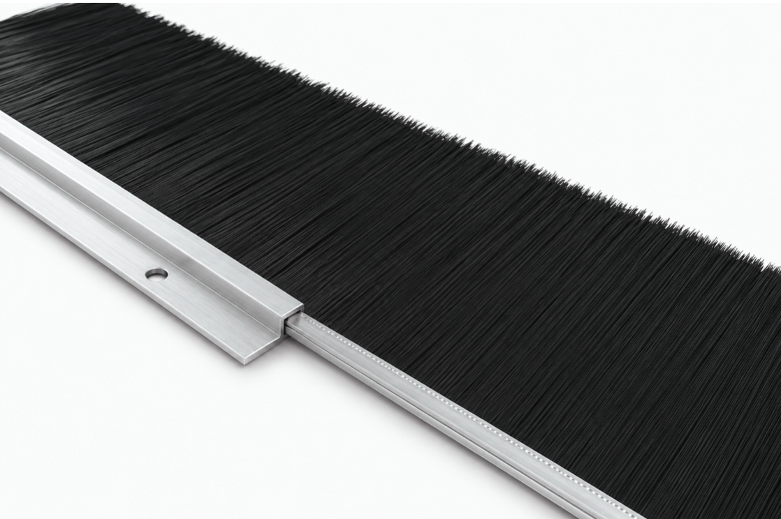
A strip brush uses filaments to cover part of an opening while allowing cables or a moving edge to pass. In a metal-channel design, the filaments form a flexible working edge while a formed carrier supports them. A separate holder may set the mounting angle and position. Flexibility here describes the filament contact, not a bendable brush backing.
Along a long, mostly straight containment edge, metal-channel strip brushes may cover a gap while keeping access practical. Potential locations include selected cable-tray passages, cabinet edges, or the meeting line between an enclosure panel and an adjacent surface. The carrier and holder must fit the mounting space and place the filament tips across the gap, rather than merely beside it. A custom-formed section may suit some curved routes, but its geometry must be specified before manufacture.
A rack panel or floor grommet may be simpler where the opening matches a standard assembly. Foam or a blanking panel may suit an opening that does not need repeated access. The decision follows the boundary and the required access, rather than a preference for any one brush style.
Specify the installed geometry, not just brush length
A strip-brush specification should show the opening, mounting face, carrier and holder cross-sections, filament direction, working gap, and cable or panel movement. Record the gap at several points along the run, including the largest expected opening. For a long assembly, show joints, supports, and whether sections can be installed separately. A nominal channel size alone does not confirm holder fit.
Brush height needs a clear datum. Exposed filament trim is measured from the channel exit to the tips; overall height also includes the carrier and may be interpreted differently once a holder is added. Mark the measurement points on the drawing. Otherwise, two suppliers can quote the same height while proposing different working reach.
Material and mounting details matter just as much. Confirm the channel section, holder angle, fixing holes or clips, filament material, diameter, fill density, cable clearance, and required contact. Long or lightly filled filaments may deflect under airflow or contact, so reach on paper does not prove installed coverage. Check that the holder retains the brush and that the contact does not force a cable beyond its permitted bend. Use a sample where fit or retention is uncertain.
If the project calls for flame-retardant, static-control, or low-shedding materials, state the required standard, test method, and documentation. A generic material name does not establish those properties. Nor does a brush automatically provide an airtight, dust-rated, or fire-rated assembly.
Protect access and safety during the retrofit
Cable routes change after commissioning. A closure that is difficult to reopen may be displaced during maintenance and left out of position. Check whether the brush can be fitted around existing cables, whether cable supports carry the load, and whether the mounting edge could abrade a cable jacket. After a cable change, inspect the affected boundary again.
The boundary may also have requirements beyond airflow. ASHRAE notes that containment designs can affect fire detection and suppression arrangements. If a cable route penetrates a fire-resistance-rated wall or floor, use the specified tested firestop system; a standard brush strip is not its replacement. The containment designer and fire-protection team should review any new barrier that changes access or discharge paths.
Verify the result at the equipment
Sealing a gap does not guarantee an energy saving. Establish whether it crosses a meaningful pressure boundary, then compare conditions before and after the change under similar IT loads and cooling-control settings. Record temperatures at affected equipment intakes, pressure difference across the boundary where measurable, supply and return conditions, and fan operating data. Facility-wide PUE alone cannot isolate the effect of one brush assembly.
If conditions do not improve, investigate other openings, obstructions, controls, or capacity limits. If they improve, record the installed details for future cable work.
For each opening, define the boundary it must maintain and how staff will use it. A metal-channel strip brush may fit a linear or specified formed path where cable access must remain practical. Verify the installed result as part of the complete cooling system.