

Choosing the right miniature circuit breaker (MCB) for a three-phase motor is crucial for electrical safety and efficient performance. The key to selecting the appropriate MCB lies in understanding the motor’s voltage, current draw, and starting characteristics, along with adhering to relevant electrical codes. This choice not only protects the motor from overloads and short circuits but also ensures uninterrupted operation.
Many engineers and technicians face challenges when sizing MCBs, as it requires balancing technical details with practical needs. It is essential to consider factors such as the motor’s rated power, efficiency, and inrush current during startup. By following the correct guidelines and calculations, one can significantly reduce the risk of equipment failure and enhance system reliability.
Understanding the specifications of different MCB types is also vital. For three-phase motors, selecting the right breaker can prevent costly downtime and enhance safety. With the right knowledge and tools, anyone can make informed decisions about protecting their three-phase motor systems effectively.
Understanding MCBs and Their Role in Motor Circuits
Motor protection is crucial for ensuring the safe and reliable operation of three-phase motors. Choosing the right Miniature Circuit Breaker (MCB) or Motor Protection Circuit Breaker (MPCB) is essential for safeguarding against overloads and short circuits. This section explores key aspects of MCB functionality and their applications in motor circuits.
What Is an MCB and How Does It Work?
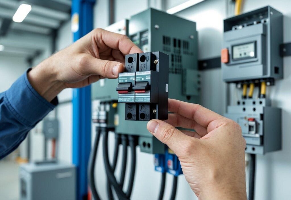
A Miniature Circuit Breaker (MCB) is an automatic switch designed to protect electrical circuits from damage caused by overcurrent. Unlike traditional fuses, MCBs can reset after a fault. They work by detecting excess current, which can occur during overloads or short circuits.
When a fault occurs, the MCB reacts quickly, breaking the circuit to prevent damage. There are different types of MCBs, including thermal-magnetic breakers, which use heat and magnetic forces to trip. Motor circuits benefit significantly from MCBs because they ensure that electric motors operate within safe limits, protecting the motor windings and associated control equipment.
Types of Circuit Breakers for Motors
For three-phase motors, various circuit breakers can provide protection. The three most common types are:
- MPCB (Motor Protection Circuit Breaker): Specifically designed for motors, MPCBs offer overload, short-circuit, and phase failure protection. They are efficient for managing motor starts and stops.
- Molded Case Circuit Breaker (MCCB): Often used for larger motors, MCCBs can handle higher currents. These are ideal for industrial applications where motors may face considerable inrush currents.
- Air Circuit Breaker (ACB): ACBs protect larger circuits from overloads and short circuits, often used in high-voltage applications. They are more common in large electrical installations, including motor control centers.
MCB Trip Curves and Selection for Inrush Current
When selecting an MCB for three-phase motors, understanding trip curves is crucial. The trip curve indicates how quickly an MCB will react to different types of overloads:
- B Curve: Suitable for lighting and small loads, it trips at lower surges.
- C Curve: Ideal for motors, as it handles moderate surges, protecting against inrush current during start-up without nuisance tripping.
- D Curve: Designed for high inrush devices, it’s suitable for large motors that experience significant startup currents.
Choosing the right trip curve helps to avoid problems during motor start-up and ensures that the MCB provides adequate protection while allowing for normal operation. Selecting the appropriate MCB reinforces system reliability and longevity in motor-driven applications.
Key Data Needed for Selecting an MCB

Choosing the right Miniature Circuit Breaker (MCB) for a three-phase motor involves understanding specific details about the motor’s requirements. The critical data includes information from the motor nameplate and calculations related to current and efficiency. Here’s a closer look at the essential components needed for effective MCB selection.
Reading the Motor Nameplate
The motor nameplate provides vital information necessary for selecting an MCB. Key details include the motor’s voltage rating, full load current (FLC), and service factor. The voltage rating indicates the operating voltage for the motor, ensuring compatibility with the electrical supply.
The FLC shows the maximum current the motor will draw under normal operating conditions. This data is crucial when choosing an MCB since the rated current must be equal to or greater than the FLC.
Lastly, the service factor is a multiplier that describes the motor’s capability to operate above its rating for short periods without overheating. Understanding these values will guide the selection of an MCB that can handle the motor’s demands.
Full Load Current and Motor FLC
Full Load Current (FLC) is a crucial parameter that dictates the MCB size. It represents the current drawn by the motor when operating at full capacity. For accurate MCB selection, it’s important to read this value directly from the motor nameplate.
To determine the appropriate MCB rating, one typically uses the formula:
MCB Rating = FLC × Safety Factor
The safety factor often ranges from 1.25 to 1.5. This adjustment accommodates starting currents, which may temporarily exceed the FLC during startup.
In case of frequent starts, higher starting currents may also occur. Knowing the starting current is essential, as this value can be two to seven times the FLC. Selecting an MCB that can tolerate these surges helps prevent unnecessary tripping during operation.
Service Factor and Starting Conditions
The service factor affects how often the motor can handle overloads and inrush currents. This factor usually ranges from 1.0 to 1.6, where a higher service factor allows for better overload handling.
When selecting an MCB, the motor’s starting conditions are also important. Motors that start frequently or require high inrush current may need specific MCB types.
Tripping characteristics based on the motor type must be carefully evaluated. For instance:
- Type C MCBs can handle 5 to 10 times the rated current, making them suitable for motors.
- Type D MCBs are ideal for motors that experience very high starting currents.
Understanding these factors ensures the MCB provides both protection and reliability for the motor during operation.
Calculation Methods and Standards
Choosing the right Miniature Circuit Breaker (MCB) for a three-phase motor requires precise calculations and adherence to established standards. Understanding the methodologies for determining breaker sizes is essential for safety and efficiency.
Using the 3 Phase Motor Circuit Breaker Sizing Calculator
A user-friendly tool, the 3 Phase Motor Circuit Breaker Sizing Calculator simplifies the process of selecting an appropriate breaker. Users input key parameters, such as motor horsepower, voltage, and the type of motor. The calculator then examines these details to recommend standard breaker sizes.
For example, if a motor has a power rating of 15 kW at 400 volts, the calculator will determine the Full Load Current (FLC) using the formula:
[ FLC = \frac{(P_{out} \times 1000)}{(\sqrt{3} \times V)} ]
After calculating the FLC, the calculator suggests an MCB with adequate breaking capacity, ensuring compliance with local electrical codes. This method is efficient and minimizes calculation errors.
NEC and IEC Standards Relevant to Breaker Sizing
It is crucial to follow the National Electrical Code (NEC) and International Electrotechnical Commission (IEC) standards for breaker sizing. NEC Article 430.32 provides guidelines on overcurrent protection for motors, detailing that the MCB rating should be based on the motor’s Full Load Current.
Tables in the NEC, such as Table 430.250 and Table 430.52, offer quick reference points for selecting the correct breaker sizes. For instance, Table 430.32 specifies that MCB ratings should be 125% of the motor’s FLC for continuous duty. The IEC standards also emphasize similar calculations and safety factors when sizing circuit breakers.
Formulas and Reference Tables
Using formulas and reference tables helps maintain safety in electrical systems. The primary formula for calculating the Full Load Current (FLC) involves the power of the motor, voltage, and phase type. For a three-phase motor, the formula is:
[ FLC = \frac{(P_{out} \times 1000)}{(\sqrt{3} \times V)} ]
After determining the FLC, users refer to NEC Table 430.250 to find the appropriate standard breaker size. This table allows users to select based on FLC and provides the necessary safety margins.
Reference tables are invaluable for motor selection, offering specific guidance on the types of breakers available. Consistently consulting these formulas and tables ensures compliance with local electrical codes and enhances the safety and efficiency of electrical systems.
Balancing Protection and Performance
When selecting an MCB for a three-phase motor, balancing protection and performance is essential. The right settings can prevent nuisance tripping while ensuring safety from overloads and short circuits. This section covers important strategies to achieve that balance.
Avoiding Nuisance Tripping
Nuisance tripping can disrupt operations and lead to downtime. To avoid this issue, it is crucial to select an MCB with the appropriate tripping curve based on the motor’s characteristics. For example, Type C MCBs are suitable for motors with high starting currents, preventing unnecessary disconnections during motor startup.
It’s also important to ensure the MCB’s thermal overload relay is set correctly. A bimetallic strip in the relay reacts to heat caused by overloads, providing protection without tripping too soon. Evaluating the breaking capacity of the MCB helps ensure it can handle potential fault currents without being overly sensitive.
Coordinating Short-Circuit and Overload Protection
Coordinating short-circuit and overload protection is vital to maintaining equipment safety. MCBs should be selected to match the motor’s specifications, like its full load current and service factor. This ensures that the MCB can handle the electrical demands without failing.
Employing a two-tier protection strategy is effective. Using both an MCB and overload relays can provide comprehensive protection. While the MCB defends against short circuits, overload relays react to prolonged increases in current that could overheat the motor. This combination maximizes safety while minimizing disruptions during normal operational fluctuations.
Addressing Voltage Drop and Installation Factors
Voltage drop can significantly impact a motor’s efficiency. Ensuring that the electrical installation minimizes voltage drops involves selecting the right cable sizes and lengths. Using appropriate conductors can maintain voltage levels within acceptable limits, avoiding performance issues that could lead to nuisance tripping.
Installation factors also influence performance. The MCB’s location should allow for easy access for maintenance and monitoring. Additionally, placing the MCB close to the motor reduces the length of the wiring, which helps prevent voltage drops. Proper sizing of the circuit breaker is critical; an appropriately sized MCB ensures that the entire electrical system delivers optimal performance without risking safety.
Best Practices for Safe and Compliant Electrical Installations
When working with electrical installations, it is essential to follow established guidelines to ensure both safety and compliance. Understanding local electrical codes, appropriately selecting motor starters, and ensuring ongoing safety measures can contribute significantly to a successful setup.
Adapting to Local Electrical Codes
Local electrical codes define the standards that must be met during installations. These codes vary by region and are designed to enhance safety and reliability.
Electrical professionals must familiarize themselves with the relevant code requirements, as they cover key areas like:
- Wiring methods
- Breaker ratings
- Grounding practices
Failure to follow these codes can lead to legal issues and safety hazards. It is advisable to consult the National Electrical Code (NEC) or other regional regulations. Checking with local authorities can also provide insight into any updates or specific requirements.
MCB Selection for Different Motor Starters
Miniature Circuit Breakers (MCBs) play a vital role in protecting three-phase motors. They are selected based on the motor’s characteristics and the type of starter used.
Key factors to consider include:
- Rated Current: The MCB must match the full load current of the motor.
- Type of Motor Starter: Different starters (e.g., direct on line, star-delta) will impact MCB selection.
- Breaking Capacity: MCBs should have enough breaking capacity to safely handle fault conditions.
For instance, if a star-delta starter is used, selecting an MCB with a suitable rating that can accommodate the starting current is crucial. Professionals should always refer to manufacturer guidelines and local codes when determining the right MCB.
Ensuring Ongoing Electrical Safety
Electrical safety is not just about initial installation; it involves ongoing maintenance and monitoring. Regular inspections can identify wear or potential issues before they lead to failures or hazards.
Best practices for ongoing safety include:
- Routine Testing: Conduct regular tests on MCBs and other protection devices.
- Visual Inspections: Look for signs of damage to wiring or components.
- Update Documentation: Keep records of inspections and changes to the electrical system.
Incorporating smart monitoring solutions can enhance safety by providing real-time data. Being proactive helps maintain a safe working environment and ensures compliance with electrical safety standards.